
|
|
|
Jeep FAQ How-To Articles Quick Reference Product Reviews My Buildup Random Home |
Hooking up offroad lights: Think of relays as an electronically controlled switch. When voltage is applied an electric magnet is energized inside, and brings two contacts together. This picture will help explain how a relay works. 
Relays are handy to use to prevent switches, or circuits from being overloaded. In the Jeep community a common use of relays is for powering offroad lights, however, the factory also uses them to power various systems on the Jeep. Almost all standard relays you buy, will look like this, and be numbered like the above picture. 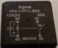
85: Ground 30: Battery/Power Source 87: What ever you want to power, like FogLights 86: When you want to turn the relay on, you power this pin. So say your foglight switch would go to this one. Whenever 86 gets power the relay will "turn on", so you'll probably want to use a switch in there so you can turn it off. If you can't turn it off somehow you might as well have wired it straight to the battery. Note that you can also feed 86 constant power and switch the ground side instead if you wish. Here is a basic wiring diagram for a relay. 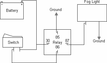
You can power the switch from pin 30 like you mentioned, however if you directly wire pin 86 and 30 together the relay will always be on. This animation should show what gets power when: 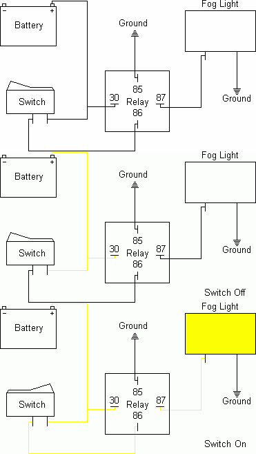
With the switch off, only one side of the switch has power, and pin 30 has power (shown in yellow in the drawing). When the switch is flipped, the other switch pin gets power, and powers pin 86, one 86 has power, the circuit is completed and pins 30 and 87 are connected directly inside the relay, the relay is now "on" and your accessory (a fog light in this case) should be on. Also note the switches power doesn't have to come from pin 30, the switches power could come from any 12+ volt source. In the picture below the switches power comes from a power source that is only hot when the key is on, this way everything will shutoff when you turn the key off, whether you remember to flip the switch or not. 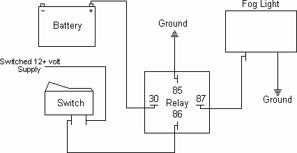
Now also note that you can switch the ground side as well. This has become my preferred method for hooking up relays actually. It means you only have to run one wire into the cab, then just ground the other side of the switch the closest piece of metal. 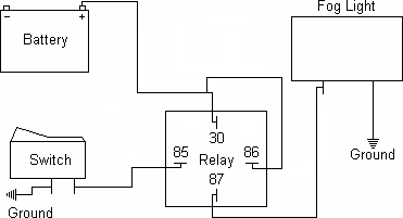
To test the relay, ground pin 85, then give pin 86 12 volts. The relay should click. If it does, you can be pretty sure that it is good. However if you wish to further check it, get out a multi-meter, and select ohms. Use some alligator clips or have someone hold the test leads on pins 87 and 30, the meter should read infinity. Now when you ground pin 85, and give pin 86 12 volts, you should get no resistance. You should be able to watch the meter show the relay opening and closing as you you apply and take away power from pin 86. Related Topics: | Relays - | Proper Wiring: | |
| © Copyright 2006 - 2025 Mike Lee | |